
Table of Contents
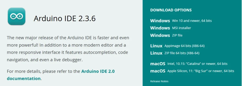
Click the below button to download the arduino software
Process for Uploading Code in Arduino
Step by Step Video Tutorial to build a Two Wheel Chassis Car Model
Experiment 1: LCD Display Using Arduino
Objective: This experiment aims to introduce students to the basics of interfacing a character LCD with an Arduino using the I2C communication protocol. By the end of this activity, students will be able to display messages on an LCD screen and understand how data is sent digitally from the microcontroller to an output device.
Working Principle: LCDs display characters based on the electrical signals they receive. The 16×2 LCD has 2 rows and 16 columns that can each show a character. Normally, many wires are needed to control the LCD, but by using an I2C module, only two pins (SDA and SCL) are needed for communication. The Arduino sends data and commands to the LCD through the I2C bus, and the display responds accordingly.
Key Concepts:
- Digital communication protocols (I2C)
- Character mapping and addressing
- Display control logic
Components:
- Arduino Uno
- I2C 16×2 LCD
- Jumper Wires
Circuit Connections:
| Component | Connection |
| VCC | 5V on Arduino |
| GND | GND on Arduino |
| SDA | A4 on Arduino Uno |
| SCL | A5 on Arduino Uno |
Code:
#include <Wire.h>
#include <LiquidCrystal_I2C.h>

LiquidCrystal_I2C lcd(0x27, 16, 2);

void setup() { lcd.begin(); lcd.backlight();
lcd.setCursor(0, 0);
lcd.print("Hello, Arduino!");
}
void loop() { }
Experiment 2: Serial Communication with PC
Objective: The goal of this experiment is to help students understand how microcontrollers like Arduino can communicate with external devices such as a computer. Through this activity, students will learn how to send and view data from the Arduino in real-time using the Serial Monitor.
Working Principle: Serial communication allows data to be transferred one bit at a time through a communication channel. The Arduino uses UART (Universal Asynchronous Receiver Transmitter) protocol to send text messages through its USB connection. The computer receives this data and displays it in the Serial Monitor. This method is especially useful for debugging and monitoring sensor data.
Key Concepts:
- UART (Universal Asynchronous Receiver Transmitter)
- Baud rate synchronization
- Serial Monitor
Components:
- Arduino Uno
- I2C 16×2 LCD
- Jumper Wires
Circuit Connections:
| Component | Connection |
| USB Cable | Connect Arduino to PC |
Code:
void setup() {
Serial.begin(9600);
}
void loop() {
Serial.println("Hello from Arduino!"); delay(1000);
}
Experiment 3: LDR Sensor Project
Objective: This experiment aims to help students measure the intensity of ambient light using an LDR (Light Dependent Resistor) and Arduino. It builds foundational knowledge of how analog sensors work and introduces the concept of using sensors to perceive the environment.
Working Principle: An LDR changes its resistance based on the light falling on it—resistance decreases with more light and increases in darkness. When combined with a resistor to form a voltage divider circuit, it creates a variable voltage that the Arduino can read through its analog input pin. This analog value helps determine the light intensity in the surroundings.
Key Concepts:
- Voltage divider circuit
- Analog-to-digital conversion (ADC)
- Light sensing and automation
Components:
- Arduino Uno
- LDR Sensor
- 10kΩ Resistor
- Jumper Wires
Circuit Connections:
| Component | Connection |
| LDR | One leg to 5V, other to A0 and one end of 10kΩ to GND |
Code:
int ldrPin = A0;
int ldrValue = 0;
void setup() {
Serial.begin(9600);
}
void loop() {
ldrValue = analogRead(ldrPin); Serial.println(ldrValue);
delay(1000);
}
Experiment 4: Temperature and Humidity Monitor
Objective: The objective of this experiment is to monitor real-time environmental conditions such as temperature and humidity using a digital sensor (DHT11) and display the readings on the Serial Monitor. It teaches students how to collect environmental data using sensors.
Working Principle: The DHT11 sensor contains a thermistor and a capacitive humidity sensor. It converts analog signals to digital internally and sends the data to the Arduino through a single digital pin using a proprietary one-wire protocol. The Arduino receives this data and can print it out or use it for automated responses in projects like smart greenhouses.
Key Concepts:
- Digital sensors and protocols
- Environmental monitoring
- Sensor calibration and reliability
Components:
- Arduino Uno
- DHT11 Sensor
- 10kΩ Resistor
- Jumper Wires
Circuit Connections:
| Component | Connection |
| VCC | 5v |
| GND | GND |
| Data | D2 (with pull-up 10kΩ to VCC) |
Check the YouTube Video Tutorial
Code:
#include "DHT.h"
#define DHTPIN 2
#define DHTTYPE DHT11
DHT dht(DHTPIN, DHTTYPE);
void setup() {
Serial.begin(9600);
dht.begin();
}
void loop() {
float h = dht.readHumidity();
float t = dht.readTemperature();
Serial.print("Temp: "); Serial.print(t);
Serial.print(" *C, Humidity: ");
Serial.print(h); Serial.println(" %");
delay(2000); }
Experiment 5: Automatic Toll Gate Using IR and Servo
Objective: The purpose of this experiment is to simulate an automatic toll gate system where an IR sensor detects an object (like a vehicle), and a servo motor opens and closes the gate. Students will learn about automation, obstacle detection, and actuator control.
Working Principle: The IR sensor detects objects by emitting infrared light and checking for reflections. When an object is present, the sensor sends a LOW signal to the Arduino. The Arduino then sends a PWM signal to the servo motor to rotate its arm, simulating a toll gate opening. After a few seconds, the arm returns to its original position. This mimics how automatic gates work in real life.
Key Concepts:
- IR proximity sensing
- PWM (Pulse Width Modulation)
- Automation logic
Components:
- Arduino Uno
- IR Sensor
- 1Servo Motor
- Jumper Wires
Circuit Connections:
| Component | Connection |
| R Sensor VCC | 5v |
| IR Sensor GND | GND |
| IR Sensor OUT | D2 |
| Servo Signal | D9 |
Check the YouTube Video Tutorial
Code:
#include
Servo myservo;
int irSensor = 2;
int val;
void setup() {
myservo.attach(9);
pinMode(irSensor, INPUT);
myservo.write(0);
}
void loop() {
val = digitalRead(irSensor);
if (val == LOW) {
myservo.write(90);
delay(3000); myservo.write(0);
}
}
Buy this Amazing Robotics Arduino Kit that comes with Interesting 8+ Experiments.
Experiment 6: Line Follower Bot using 2 IR Sensors and 2 BO Motors
Objective: To design a line follower robot that uses two IR sensors to detect and follow a black line on a white surface.
Working Principle: IR sensors detect the black line by sensing the difference in reflected infrared light. The Arduino processes this sensor data and drives the motors accordingly to keep the bot on track.
Basic Logic:
- Left sensor on line: turn left
- Right sensor on line: turn right
- Both sensors on line: move forward
- Both sensors off line: stop
Components:
- Arduino Uno – 1
- IR Sensors – 2
- BO Motors– 2
- Motor DriverModule (L298N or L293D) – 1
- Robot Chassis– 1
- Wheels – 2
- Battery – 1
- Jumper Wires – As needed
Code:
#define LS 2
#define RS 3
#define LM1 4
#define LM2 5
#define RM1 6
#define RM2 7

void setup() { pinMode(LS, INPUT); pinMode(RS, INPUT); pinMode(LM1, OUTPUT); pinMode(LM2, OUTPUT); pinMode(RM1, OUTPUT); pinMode(RM2, OUTPUT);
}

void loop() {
int left = digitalRead(LS); int right = digitalRead(RS);
if (left == 0 && right == 0) forward();
else if (left == 0 && right == 1) leftTurn(); else if (left == 1 && right == 0) rightTurn();
else stopBot();
}
void forward() { digitalWrite(LM1, HIGH); digitalWrite(LM2, LOW); digitalWrite(RM1, HIGH); digitalWrite(RM2, LOW);
}

void leftTurn() { digitalWrite(LM1, LOW); digitalWrite(LM2, HIGH); digitalWrite(RM1, HIGH); digitalWrite(RM2, LOW);
}

void rightTurn() { digitalWrite(LM1, HIGH); digitalWrite(LM2, LOW); digitalWrite(RM1, LOW); digitalWrite(RM2, HIGH);
}

void stopBot() { digitalWrite(LM1, LOW); digitalWrite(LM2, LOW); digitalWrite(RM1, LOW); digitalWrite(RM2, LOW);
}
Experiment 7: Robo Race Bot using HC-05 Bluetooth Module
Objective: To build a Bluetooth-controlled robot that participates in a Robo Race. Controlled wirelessly via an Android app using the HC-05 module.
Working Principle: Commands are sent from a mobile app and received by the HC-05.Arduino then executes motor control based on command values.
Bluetooth Commands:
- F → Forward
- B → Backward
- L → Left
- R → Right
- S → Stop
Components:
- Arduino Uno – 1
- HC-05 Bluetooth Module – 1
- Motor Driver Module – 1
- BO Motors– 2
- Robot Chassis– 1
- Battery – 1
- Smartphone + Bluetooth controller app
Code:
char data; void setup() {
Serial.begin(9600); pinMode(2, OUTPUT); pinMode(3, OUTPUT); pinMode(4, OUTPUT); pinMode(5, OUTPUT);
}

void loop() {
if (Serial.available()) { data = Serial.read();
if (data == 'F') forward();
if (data == 'B') backward(); if (data == 'L') left();
if (data == 'R') right();
if (data == 'S') stopBot();
}
}
void forward() { digitalWrite(2,HIGH); digitalWrite(3,LOW); digitalWrite(4,HIGH); digitalWrite(5,LOW); }
void backward() { digitalWrite(2,LOW); digitalWrite(3,HIGH); digitalWrite(4,LOW); digitalWrite(5,HIGH); }
void left() { digitalWrite(2,LOW); digitalWrite(3,HIGH); digitalWrite(4,HIGH); digitalWrite(5,LOW); }
void right(){ digitalWrite(2,HIGH); digitalWrite(3,LOW); digitalWrite(4,LOW); digitalWrite(5,HIGH); }
void stopBot() { digitalWrite(2,LOW); digitalWrite(3,LOW); digitalWrite(4,LOW); digitalWrite(5,LOW); }
Experiment 8: Obstacle Avoiding Bot using Ultrasonic Sensor and Servo Motor
Objective: To create a robot that automatically detects and avoids obstacles using an ultrasonic sensor and a servo motor.
Working Principle: The ultrasonic sensor measures distance to objects. If an obstacle is detected within a certain range, the servo rotates to scan left and right. The bot then moves in the direction with more clearance.
Components:
- Arduino Uno – 1
- Ultrasonic Sensor – 1
- Servo Motor – 1
- BO Motors– 2
- Motor Driver Module – 1
- Robot Chassis– 1
- Jumper Wires – As needed
- Battery – 1
Code:
#include<Servo.h>
Servo servo;
int trig = 9; int echo = 10;
long duration;
int distance;
void setup() { Serial.begin(9600);
pinMode(trig, OUTPUT);
pinMode(echo, INPUT);
servo.attach(6);
}
void loop() {
digitalWrite(trig, LOW);
delayMicroseconds(2);
digitalWrite(trig, HIGH);
delayMicroseconds(10);
digitalWrite(trig, LOW);
duration = pulseIn(echo, HIGH);
distance = duration * 0.034 / 2;

if (distance < 20) {
servo.write(90);
delay(1000);
servo.write(0);
delay(1000); servo.write(180);
delay(1000);
} else {
// Move forward
}
}
Experiment 9: Voice Controlled Robot using Arduino and Bluetooth
Objective: To build a voice-controlled robot using ArduinoUno, HC-05, and BO motors controlled wirelessly by voice commands from a Bluetooth app.
Working Principle: Voice commands like “forward”, “left”, etc., are sent from the app. Arduinoreceives them via HC-05 and drives the motors accordingly.
Components:
- Arduino Uno – 1
- HC-05 Bluetooth Module – 1
- BO Motors– 2
- Motor Driver– 1
- Robot Chassis– 1
- Battery – 1
- Bluetooth Voice Control App
Code:
char command;
#define
IN1 2
#define IN2 3
#define IN3 4
#define IN4 5
void setup() {
Serial.begin(9600);
pinMode(IN1, OUTPUT);
pinMode(IN2, OUTPUT);
pinMode(IN3, OUTPUT); pinMode(IN4, OUTPUT);
}
void loop() {
if (Serial.available() > 0) { command= Serial.read();
switch (command) {
case 'F': forward();
break; case 'B': backward(); break;
case 'L': left(); break;
case 'R': right();
break; case 'S': stopBot();
break;
}
}
}
void forward() { digitalWrite(IN1, HIGH); digitalWrite(IN2, LOW); digitalWrite(IN3, HIGH); digitalWrite(IN4, LOW); }

void backward() { digitalWrite(IN1, LOW); digitalWrite(IN2, HIGH);digitalWrite(IN3, LOW); digitalWrite(IN4, HIGH); }

void left() { digitalWrite(IN1, LOW); digitalWrite(IN2, HIGH);digitalWrite(IN3, HIGH); digitalWrite(IN4, LOW); }

void right() { digitalWrite(IN1, HIGH); digitalWrite(IN2, LOW); digitalWrite(IN3, LOW); digitalWrite(IN4, HIGH); }

void stopBot() { digitalWrite(IN1, LOW); digitalWrite(IN2, LOW); digitalWrite(IN3, LOW); digitalWrite(IN4, LOW); }
Check the YouTube Video Tutorial
Buy this Amazing Robotics Arduino Kit that comes with Interesting 8+ Experiments.